Grid power is AC for many good reasons, yet almost every device requires DC power to operate. This means that AC-DC power supplies are used almost everywhere, and, in a time of environmental awareness and rising energy costs, their efficiency is critical to controlling operating costs and using energy wisely.
Simply put, efficiency is the ratio between input power and output power. However, the input power factor (PF) must be considered – this is the ratio between useful (true) power and total (apparent) power in any AC-powered device – including power supplies.
With a purely resistive load, the PF will be 1.00 (‘unity’) but a reactive load will decrease the PF as the apparent power rises, leading to reduced efficiency. A less-than-unity PF results from out-of-phase voltage and current, a significant harmonic content, or a distorted current waveform – common in discontinuous electronic loads such as switched mode power supplies (SMPS).
PF Correction
Given the impact on efficiency that a low PF has, when power levels are above 70W, legislation requires designers to incorporate circuitry that will correct the PF to a value close to unity. Often, active PF correction (PFC) employs a boost converter that converts rectified mains to a high DC level. This rail is then regulated using pulse width modulation (PWM) or other techniques.
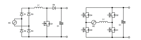
This approach generally works and is simple to deploy. However, modern efficiency requirements such as the challenging ‘80+ Titanium standard’ stipulate the efficiency across a wide operating power range, requiring peak efficiencies of 96% at half load. This means the line rectification and PFC stage must achieve 98% as the following PWM DC-DC will lose a further 2%. Achieving this is very challenging due to the losses within the diodes in the bridge rectifier.
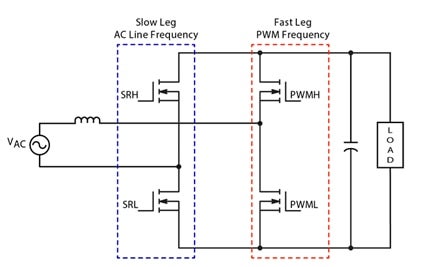
Replacing the boost diode with a synchronous rectifier helps and the two line rectifier diodes can be similarly replaced which further enhances efficiency. This topology is referred to as totem pole PFC (TPPFC) and, in theory, with an ideal inductor and perfect switches, efficiency will approach 100%. While silicon MOSFETs offer good performance, wide bandgap (WBG) devices offer far closer to ‘ideal’ performance.
Dealing with Losses
As designers increase frequency to reduce the size of magnetic components, dynamic losses in switching devices will also increase. As these losses can be significant with silicon MOSFETs, designers are turning to WBG materials including Silicon Carbide (SiC) and gallium nitride (GaN) - especially for TPPFC applications.
Critical conduction mode (CrM) is generally the preferred approach for TPPFC designs at power levels up to a few hundred watts, balancing efficiency and EMI performance. In kilowatt designs, continuous conduction mode (CCM) further reduces RMS current within switches, reducing conduction loss.
Even CrM, can see an efficiency drop approaching 10% at light loads which is a roadblock to achieving ‘Titanium 80 Plus’. Clamping (‘folding-back’) the maximum frequency forces the circuit into DCM at light loads, thereby significantly reducing peak currents.
Overcoming Design Complexity
With four active devices to be driven synchronously and the need to detect the inductor’s zero current crossing to force CrM, TPPFC design can be far from trivial. Additionally, the circuit must switch in / out of DCM while maintaining a high-power factor and generating a PWM signal to regulate the output – as well as providing circuit protection (such as over current and over voltage).
The obvious way to address these complexities is to deploy a microcontroller (MCU) for the control algorithms. However, this requires the generation and debugging of code, which add significant effort and risk to the design.
CrM- based TPPFC without Coding
However, time-consuming coding can be avoided by using a fully integrated TPPFC control solution. These devices offer several advantages including high performance, faster design time and reduced design risk as they eliminate the need to implement a MCU and associated code.
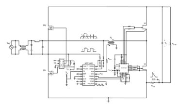
A good example of this type of device is onsemi’s NCP1680 mixed-signal TPPFC controller that operates in constant on-time CrM, thereby delivering excellent efficiency across a wide load range. The integrated device features ‘valley switching’ during frequency foldback at light loads to enhance efficiency by switching at a voltage minimum. The digital voltage control loop is internally compensated to optimize performance throughout the load range, while ensuring that the design process remains simple.
The innovative TPPFC controller includes a novel low-loss approach for current sensing and cycle-by-cycle current limiting offers substantial protection without the need for an external Hall-effect sensor, thereby reducing complexity, size and cost.
Figure 4: NCP1680 Typical Application Schematic
A full suite of control algorithms is embedded within the IC, giving designers a low-risk, tried-and-tested solution that delivers high performance at a cost-effective price point.
Watch Meet Ultra-High-Density Design Challenges with 300 W Totem Pole PFC and LLC Power Supply and learn more about the NCP1680.