公司介绍
电流检测设计工具

流畅简单的设计过程
电流检测设计工具将分步骤带领您完成系统输入、元器件选择和性能评估,简化了通常的迭代过程,从而快速创建优化的分流式检测解决方案。
输入页面
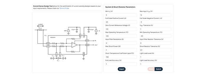
输入页面收集关键系统要求,如电源电压、共模范围、电流限制、基准设置和预期放大器温度等。
这些参数的输入将为器件推荐、单/双向电流感应选择等提供指导,并纳入分流功率、容差和温度系数假设。可选输入滤波器电阻和容差效应,增加了增益、偏移和温度相关误差,同时瞬态行为不会被建模。在输入所有参数后,您可以提交数据,以进入工作表设计阶段,优化解决方案、保存设计或重置为默认值。
工作表设计页面
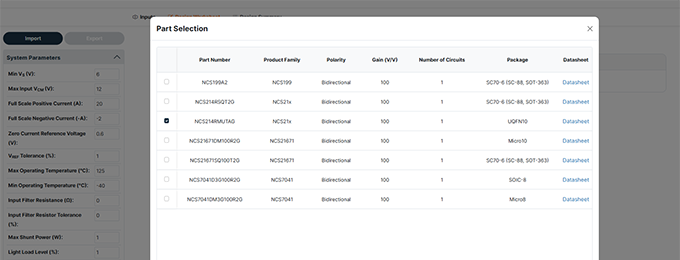
参数输入提交后,会出现一个器件选择窗口,显示推荐的放大器、增益选项、封装和对应的数据手册链接。
选择器件后,“工作表设计”会提供可视化反馈,如标称输出电压和最坏情况下的上下限,并在超出输出限制时进行提醒。
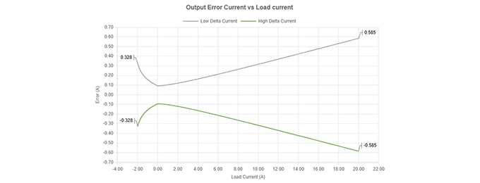
误差曲线
此外,工作表设计页面还提供了直流误差性能的两个互补视图,显示了系统的精确度以及在整个工作范围内实际安全电流量。
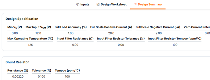
设计摘要
设计摘要页面显示设计规格、分流特性、设计结果和所选放大器的器件规格以及原理图和误差曲线。
打印此页时可采用 PDF信函格式。
视频教程
电流检测设计工具FAQ
电流检测设计工具简化了分流式电流检测解决方案的迭代过程,能够评估放大器数据手册参数、分流特性和系统要求,以预估不同负载条件下的系统准确性、功率损耗和性能表现。
这个工具纳入了放大器的极值最小/最大规格,包括
- 增益误差
- 失调电压和漂移
- CMRR
- PSRR
- 输入偏置/失调电流
- 非线性
- 温度效应
- 输入滤波器电阻器效应
必填信息包括:
- 电源电压(VS)
- 最大输入共模电压
- 满量程正电流和负电流
- 零电流基准电压(VREF)和容差
- 工作温度范围
- 输入滤波电阻值和容差
- 最大分流功率
- 分流容差和温度系数
- 期望的轻载和满载精度
设计工具将利用这些参数推荐分流数值和兼容设备。
这个设计工具可以针对输入滤波电阻对以下因素的影响进行建模:
- 增益降低
- 电阻容差引起的额外误差
- 滤波电阻和放大器输入阻抗之间的温度不匹配
- 它不会计算滤波响应或建议滤波器电容,因为这是一个纯直流精度计算器
分流电阻数值推荐是基于:
* 满量程电流
* 最大允许分流功率
* 精度要求
设计工具会选择一个在功率预算范围内同时最大化精度的分流值,其中最重要的是基于分流功率要求。
不会。这个工具是直流误差计算器,并不会对以下情况建模:
- 差分或共模瞬态
- 快速开关噪声
- 动态响应
提交系统输入后:
- “器件选择”窗口弹出。
- 设计工具基于增益、极性、运行环境推荐器件。
- 选择一个器件后进入“工作表设计”页面。
您可以修改:
* 分流电阻、容差和温度系数
* 选定的放大器增益
* 系统参数(VS、VREF、电流等)
这张工作表还提供:
* 原理图
* 引脚配置选项
* 导出/导入功能
* 实时误差和性能曲线
以下三条关键曲线有助于验证设计:
1. 输出电压vs.负载电流曲线显示额定输出和最坏情况下输出的运行边界。
2. 输出误差电流vs.负载电流以安培表示(电路可以分辨的电流值)
3. 输出精度与负载电流 (%)
例如:
* VFS > VOUT Max — 满量程输出超出放大器限制
* 量程利用率 > 100% — 输出范围被过载
* 输出电压范围误差 — 最小/最大输出超出器件规格
您可以:
- 降低分流电阻
- 降低增益
- 调整VREF
- 重新评估全量程电流范围
可以。这个工具支持:
- 从工作表导出设计文件
- 在“输入页面”或工作表页面导入设计文件
不会。它会用红色标出超出规格的结果,但您仍可以对其进行评估。
温度影响:
* 偏移漂移
* 增益漂移
* 分流电阻的温度系数
* 滤波电阻的不匹配
这个设计工具利用放大器数据手册中的最小/最大漂移值来计算最坏情况下的误差。
量程利用率 (%) = 在满量程电流下,放大器输出范围(GND至VS)中被占用的比例。
数值超过100%提示削波或输出无效。